Views: 0 Author: Site Editor Publish Time: 2026-07-31 Origin: Site
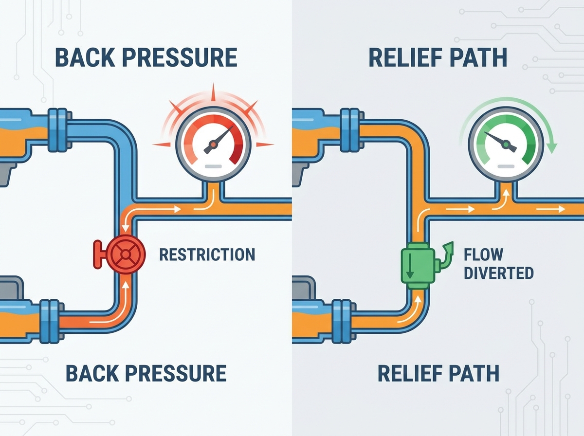
Unmanaged back pressure is a primary catalyst for premature component failure, excessive heat generation, and catastrophic seal blowouts in any industrial or mobile Hydraulic System. When fluid encounters resistance on its path back to the reservoir, the resulting pressure spikes severely degrade performance and lifespan. Identifying whether system inefficiency stems from inherent design flaws, undersized components, or degraded fluid pathways is your first priority. You must calculate the operational cost of unplanned downtime versus proactive system modification to make informed maintenance decisions. Moving beyond temporary manual pressure bleed-offs requires evaluating permanent, engineered solutions. These range from line upsizing to advanced relief valve integration. Implementing the right structural changes restores optimal flow dynamics, protects capital equipment, and ensures your machinery operates at peak efficiency without burning up pumps or blowing out return filters.
Flow Restriction is the Root Cause: Over 80% of back pressure issues in a hydraulic system originate from undersized return lines, excessive use of quick disconnects, or clogged filtration units.
Component Sizing Dictates Performance: Upgrading to adequately sized hoses and rigid pipes, while minimizing 90-degree fittings, significantly reduces fluid velocity and friction-induced pressure drops.
Valve and Accumulator Integration: Strategic deployment of pressure relief valves (PRVs), crossport reliefs, and accumulators absorbs hydraulic shock and maintains safe pressure thresholds.
Safety Precedes Maintenance: Safely bleeding residual pressure requires strict adherence to Lockout/Tagout (LOTO) procedures and complete mechanical cycling of all directional controls before breaking any connection in the hydraulic system.
Table of Contents
You must differentiate between necessary back pressure and parasitic back pressure. Necessary back pressure is required for specific actuator control, anti-cavitation measures, or braking functions. Parasitic back pressure generates waste heat and reduces mechanical efficiency. It forces the pump to work harder than necessary, wasting energy and accelerating component wear across the entire Hydraulic System. When a return line is too small, the fluid backs up, creating a bottleneck that robs the machine of usable power.
Recognizing the physical indicators of excessive pressure buildup is the first step in diagnosis. Look for elevated fluid temperatures, sluggish cylinder retraction, and weeping cylinder seals. You might also notice audible fluid aeration or cavitation, which sounds like marbles rattling inside the pump. These symptoms indicate that fluid flow is restricted. Energy converts into damaging heat and vibration instead of doing useful work.
Check the reservoir temperature gauge after one hour of normal operation.
Inspect all cylinder rod seals for weeping fluid during the retraction stroke.
Listen to the main pump for high-pitched whining or rattling noises.
Measure the cycle times of your main actuators and compare them to baseline specs.
Diagnosing leaks, weeping fittings, and premature hose failures requires close inspection at pump outlets and return line connections. These areas are prone to localized back pressure spikes. A small leak at a pump connection often signifies that the return circuit cannot handle the fluid volume efficiently. The system forces fluid out through the weakest seal. You will often find blown O-rings on flange fittings where the return line meets the tank.
Define baseline metrics for a successful intervention before making changes. Success criteria might include reducing return line pressure to manufacturer-specified tolerances, lowering operating temperatures by a specific delta, or completely eliminating hydraulic shock within the Hydraulic System. Having measurable goals ensures your modifications actually solve the root problem.
Symptom | Probable Restriction Point | Target Success Metric |
|---|---|---|
Overheating Fluid (>180°F) | Undersized return lines or clogged cooler | Reduce temp to 140°F - 160°F |
Sluggish Cylinder Retraction | Restrictive quick couplers or directional valve | Restore cycle time to OEM spec |
Blown Return Filter Housings | Excessive flow surges or cold fluid starts | Maintain return pressure below 50 PSI |
Fluid velocity and friction correlate directly with hose internal diameter (ID). You must calculate the correct nomograph values for return lines compared to pressure lines in a standard Hydraulic System. Return lines typically require a larger ID than pressure lines to maintain a lower fluid velocity, minimizing friction and subsequent back pressure. A common rule of thumb is keeping return line velocity below 10 feet per second.
Compare the pressure drop characteristics of rigid steel piping versus flexible hoses. Rigid piping generally offers smoother internal surfaces, reducing flow resistance over long runs. Flexible hoses are necessary for moving parts but introduce more friction. Evaluate when to use each to minimize overall flow resistance. Use hard lines along the boom or frame, and only use hoses where articulation is required.
Routing larger hoses or pipes in compact machinery presents physical constraints. You must balance optimal fluid dynamics with spatial limitations. Upgrading a line size might require custom routing or modifying brackets to accommodate the larger outer diameter. Evaluate the return on investment of replacing high-resistance 90-degree elbows. Using swept fittings, 45-degree bends, or straight runs significantly reduces turbulence and pressure drop. Every sharp turn in a fluid pathway acts as a restriction.
Pressure Relief Valves (PRVs) play a major role in venting excess pressure to the reservoir. You need to evaluate direct-acting versus pilot-operated relief valves based on system response time requirements. Direct-acting valves respond faster to sudden spikes. Pilot-operated valves handle higher flow rates with greater stability and less pressure override.
Adding or adjusting directional valve pilot chokes can slow spool shifting times. This adjustment reduces sudden pressure spikes and hydraulic shock in the return circuit of the Hydraulic System. Slower actuation prevents the water hammer effect that damages seals and fittings. Quick disconnects are inherently restrictive due to small internal orifices and poppet restrictions. Provide a decision framework for permanently hard-plumbing attachments where quick couplers are not strictly necessary. Removing unnecessary quick couplers instantly improves return flow and lowers back pressure.
Bladder, diaphragm, and piston accumulators absorb kinetic energy and dampen pressure transients in a high-flow Hydraulic System. They act as shock absorbers, taking in excess fluid during pressure spikes and releasing it when pressure drops, stabilizing the entire circuit.
Select the correct accumulator volume and pre-charge pressure relative to the system's maximum operating pressure and flow rate. Incorrect sizing renders the accumulator ineffective or risks bladder failure. Consult engineering parameters to match the accumulator to your specific application. Address the maintenance overhead and safety compliance requirements associated with accumulator installation. This includes periodic nitrogen pre-charge checks, installing specialized safety blocks, and integrating manual bleed valves to ensure safe depressurization during maintenance.
The mandatory first step is shutting down the prime mover, whether it is an electric motor or an internal combustion engine, and isolating the power source. This prevents accidental startup while you are working on the Hydraulic System. Lock out the main breaker or remove the ignition key.
Mechanically cycle all joysticks, levers, and control valves through their full range of motion. This action bleeds trapped fluid back to the reservoir, relieving pressure stored in the lines and cylinders. Do this multiple times to ensure all circuits are vented. Lower all implements to the ground or mechanically block cylinders before attempting to relieve pressure. Suspended loads hold immense potential energy. If a line is opened while a load is suspended, the sudden release of pressure will cause the load to drop violently.
Shut down the prime mover and apply LOTO devices.
Lower all suspended loads to the ground.
Cycle all directional control valves at least ten times.
Open the manual bleed valve on the accumulator safety block.
Use inline pressure gauges and diagnostic test ports, such as Minimess couplings, to empirically verify that pressure has dropped to zero. Never assume a system is depressurized just because the pump is off. Always verify before loosening any fittings. Address edge cases where pressure remains trapped between a closed valve, a cylinder, or disconnected quick-disconnect attachments due to thermal expansion. Use specialized micro-bleed valves or controlled fitting-cracking techniques using appropriate PPE to safely release this residual pressure.
Compare the cost and effectiveness of quick fixes versus comprehensive system overhauls. Removing a single restrictive fitting or cleaning return filters offers immediate relief but may not solve underlying design flaws. Redesigning the return manifold provides long-term reliability for the Hydraulic System. You have to weigh the cost of replacing blown hoses every month against the one-time cost of hard-plumbing a larger return line.
Evaluate how current modifications will handle future increases in pump displacement, cycle rates, or the addition of auxiliary attachments. Sizing lines and valves only for current needs guarantees you will face back pressure issues again when upgrading equipment later. Always size your return lines for at least 20% more flow than your current maximum pump output.
Modification Type | Implementation Effort | Impact on Back Pressure |
|---|---|---|
Filter Element Replacement | Low | Moderate |
Return Hose Upsizing | Medium | High |
Accumulator Installation | High | High (Shock Reduction) |
Fitting Optimization (Swept vs 90-degree) | Medium | Moderate to High |
Relieving back pressure requires a holistic evaluation of flow dynamics, component sizing, and restriction points within the machinery. Start with safe manual bleed-offs for immediate maintenance, progress to eliminating obvious flow restrictions like unnecessary couplers, and escalate to engineering upgrades for chronic issues.
Established in 2016, MDP is a Qingdao-based industrial and trade enterprise specializing in hydraulic systems, valves, pumps, motors, cylinders, filters, gauges, power units, and related components. With integrated quality control from design through delivery, ISO 9001-based testing, and customized engineering support, the company provides reliable hydraulic solutions for demanding industrial applications.
Audit your current return lines using a flow meter and pressure gauges to identify bottlenecks.
Replace all unnecessary 90-degree fittings with swept 45-degree bends or straight runs.
Hard-plumb any attachments that do not require frequent removal to eliminate quick coupler restrictions.
Install an accumulator on the return circuit if you experience severe hydraulic shock during valve shifting.
A: Acceptable back pressure varies by design but generally ranges from 15 to 50 PSI in return lines. Pressure above manufacturer specifications causes overheating and efficiency loss.
A: Quick couplers restrict flow due to small internal orifices. Hard-plumbing connections or using oversized, flat-face couplers reduces this restriction significantly.
A: While rare, excessively large return hoses can lead to fluid pooling or slower system response times in specific low-flow applications, though they generally improve back pressure issues.
A: A standard PRV vents excess pressure to the reservoir. A crossport relief valve vents pressure from one side of an actuator directly to the other, useful in bidirectional motor circuits.
A: Secure the load mechanically, then carefully use a micro-bleed valve or slowly crack the fitting at the cylinder port while wearing full PPE to bleed the trapped fluid.
A: Back pressure forces the pump to push fluid through restrictions. The energy lost to this friction converts directly into heat, rapidly raising fluid temperatures.
A: An accumulator contains a compressible gas cushion. When a pressure spike occurs, fluid enters the accumulator, compressing the gas and absorbing the shock wave before it damages components.