Views: 0 Author: Site Editor Publish Time: 2026-07-10 Origin: Site
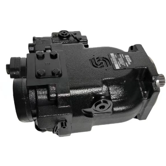
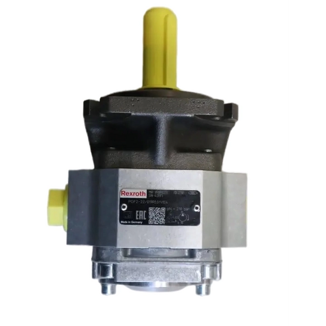
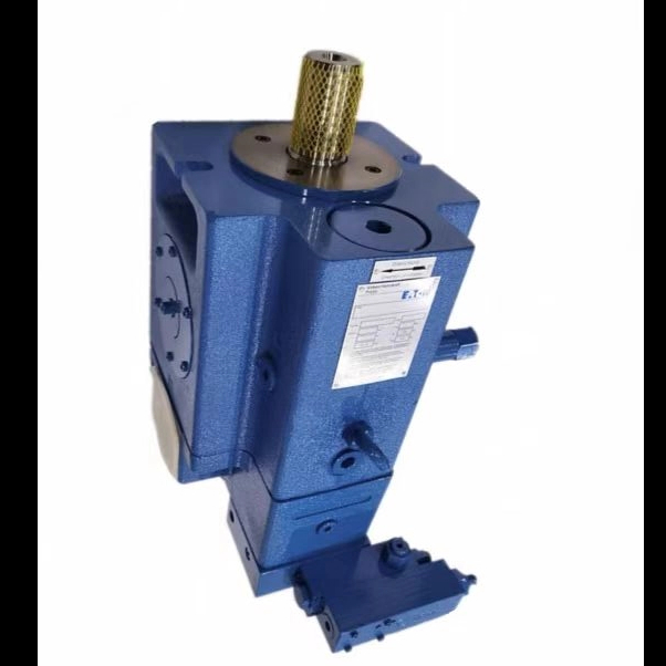
Unmitigated thermal escalation directly causes catastrophic system failure in industrial and mobile fluid power applications. When a Hydraulic Pump generates excess heat, it initiates a destructive cycle. The hydraulic oil loses viscosity rapidly, which immediately accelerates component wear. Seals degrade, harden, and fail under the thermal stress. This sequence guarantees unplanned and highly disruptive downtime that halts production lines and damages expensive machinery.
Managing this thermal load requires precise diagnostics rather than guesswork. You must distinguish between uncontrolled heat generation and actual cooling circuit failures. Treating the symptom with a larger reservoir rarely solves the underlying mechanical inefficiency. This technical framework will help you diagnose the root causes of thermal inefficiencies. You will learn to evaluate engineered cooling solutions effectively. Implementing these strategies will protect your critical hydraulic infrastructure from heat-induced destruction and extend the operational lifespan of your equipment.
Heat equals wasted energy: Overheating is a direct symptom of mechanical, volumetric, or structural inefficiencies within the hydraulic pump, cylinders, or control valves.
Viscosity is the first casualty: Operating above optimal temperature thresholds (typically 130°F–140°F / 55°C–60°C) halves the life of hydraulic oil for every 18°F (10°C) increase.
Two-front diagnostic approach: Successful troubleshooting requires isolating uncontrolled heat generation sources (e.g., bypassing valves, worn hydraulic pump internals) from cooling capacity failures (e.g., clogged heat exchangers).
Cooling requires precise sizing: Selecting a heat exchanger requires calculating the exact heat load (usually 20-30% of total input power) rather than relying on estimations.
Proactive mitigation lowers operational costs: Strategic cooling solutions and reservoir optimizations drastically reduce long-term expenses by extending fluid and hardware lifespans.
Table of Contents
Normal operating temperatures depend entirely on thermal equilibrium. A successful system maintains a state where heat dissipation equals heat generation. When generation outpaces dissipation, the system overheats rapidly. Understanding the physics behind this process is the first step in diagnosing any fluid power thermal issue.
The law of conservation of energy governs fluid power circuits. Energy not converted into mechanical work inherently becomes heat. For example, a Hydraulic Pump operating at 80% efficiency converts the remaining 20% of input power directly into thermal energy. System inefficiencies translate directly to your baseline heat load calculations. You must account for these losses when sizing cooling circuits. If an electric motor inputs 100 horsepower into the system, and the overall efficiency is 75%, you are actively generating 25 horsepower worth of heat that must be removed continuously.
Pressure drops across relief valves generate massive amounts of heat. Flow controls and undersized piping restrict fluid movement, increasing friction exponentially. Overworking hydraulic cylinders creates excessive mechanical resistance. High-pressure stalling forces fluid over relief valves continuously, which is one of the fastest ways to boil hydraulic fluid. Mismatched load demands strain the entire circuit. These conditions generate excessive mechanical and fluid friction, driving temperatures upward rapidly. Field technicians often find that simply resizing a directional control valve or replacing a restrictive fitting can drop system temperatures by several degrees.
Hydraulic oil viscosity dictates internal friction levels. Temperature spikes thin the fluid dangerously. A Hydraulic Pump working with degraded, low-viscosity fluid loses its protective lubricating film. Increased metal-to-metal contact occurs immediately. This friction generates secondary heat, compounding the initial thermal problem. The cycle accelerates until catastrophic mechanical failure stops the system. Maintaining the correct ISO viscosity grade for your specific operating temperature range is non-negotiable for system longevity.
Effective diagnostic troubleshooting requires categorizing root causes systematically. We divide these into two primary failure pathways. You must isolate Uncontrolled Heat Generation from Cooling Circuit Failures to avoid replacing the wrong components.
Internal leakage inside an aging Hydraulic Pump creates severe problems. The system works harder to maintain target pressure. This slippage creates intense localized heat zones. Continuous bypassing of relief valves is another major culprit. Oil exiting through relief valves at high pressure converts 100% of its kinetic energy into thermal energy. Aeration and cavitation also destroy efficiency. Entrained air under pressure creates micro-dieseling effects. These implosions cause extreme, localized temperature spikes that damage internal components and degrade the oil.
Check the case drain flow on variable displacement pumps to measure internal leakage.
Inspect all relief valves to ensure they are set at least 200 PSI above the compensator setting.
Listen for the distinct whining or gravel-like sound of cavitation near the pump inlet.
Verify that directional valves are shifting fully and not hanging up mid-stroke.
Low fluid levels in the reservoir speed up heating. Reduced fluid volume decreases the oil's dwell time. This prevents adequate passive heat dissipation and air release. Clogged or fouled heat exchangers block thermal transfer. External dust buildup on radiator fins insulates the cooler. Internal mineral scaling in water tubes restricts flow. Environmental factors also play a massive role. High ambient temperatures reduce the cooling delta. Poor ventilation traps hot air around the equipment. Proximity to external heat sources like combustion engines adds external thermal loads.
Overheating directly impacts operational costs and safety risks. Ignoring thermal warnings guarantees expensive mechanical consequences and extensive production delays.
Elevated temperatures accelerate fluid oxidation exponentially. The Arrhenius equation dictates this chemical breakdown. High heat leads directly to varnish and sludge formation. The hydraulic oil turns darkened and blackened quickly. Degraded oil loses its ability to lubricate and protect metal surfaces. Varnish coats valve spools, causing them to stick, which leads to erratic machine operation and further heat generation.
Common elastomer seals have strict thermal limits. Nitrile and Viton compounds degrade under extreme heat. Hardening, cracking, or melting occurs rapidly. This degradation leads to external leaks and internal pressure loss. Once seals fail, the Hydraulic Pump cannot maintain volumetric efficiency. Replacing a blown shaft seal requires removing the pump entirely, resulting in hours of lost production.
Overheating carries a heavy financial burden. Fluid replacement costs multiply as oil degrades faster. Premature rebuilds drain maintenance budgets. Lost production hours halt revenue generation. Managing temperatures proactively prevents these cascading financial losses. A single catastrophic pump failure often costs ten times more than installing a properly sized heat exchanger.
Restoring thermal equilibrium requires specific engineered approaches. You can utilize passive design elements or active mechanical cooling systems depending on your application parameters.
Reservoir size dictates natural convection cooling capacity. Proper baffling forces oil to travel a longer path. This maximizes dwell time and surface area contact. Passive cooling has strict limitations. It fails in high-duty-cycle applications. High-ambient-temperature environments overwhelm passive dissipation entirely. As a general rule, the reservoir should hold three to five times the pump's gallon-per-minute output, but space constraints often make this impossible on mobile equipment.
Forced-air coolers utilize radiator and fan assemblies. Ambient air blows across finned tubes to remove heat. They offer easy installation and lower maintenance requirements. However, they generate high noise levels. Their efficiency depends entirely on the ambient air temperature. If the ambient air is 100°F, you cannot cool the oil below 115°F without a massive, oversized radiator core.
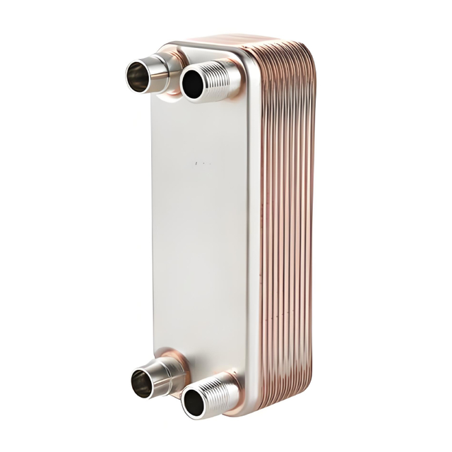
Shell-and-tube and brazed plate heat exchangers use water for thermal transfer. They provide superior heat transfer rates. Their compact footprints save valuable machine space. They require a continuous, clean water supply. You must also manage the risk of fluid cross-contamination if internal tubes rupture. Brazed plate coolers offer incredible efficiency but cannot be mechanically cleaned if they become fouled with scale.
Cooling Method | Primary Advantage | Primary Limitation | Best Application Environment |
|---|---|---|---|
Passive Reservoir | Zero energy consumption | Insufficient for high heat loads | Low-duty, indoor industrial |
Air-Cooled | Easy installation, no water needed | Dependent on ambient air temp | Mobile equipment, remote sites |
Water-Cooled | Maximum heat transfer in small footprint | Requires clean, continuous water | Heavy industrial, high-heat load |
Specify cooling hardware based on empirical data. Guesswork leads to undersized coolers and continued overheating. You must calculate the exact thermal load before purchasing any hardware.
Determine the exact heat load before purchasing equipment. Calculate the percentage of input horsepower lost to heat. The approach temperature is critical here. This is the difference between entering oil temperature and entering cooling medium temperature. A larger approach temperature allows for a smaller, less expensive cooler. Always size the cooler for the worst-case scenario, such as peak summer temperatures combined with maximum machine duty cycles.
Compare the footprint and weight of different solutions. Evaluate your utility requirements carefully. Airborne debris dictates fin spacing on air-cooled units. Tight fin spacing clogs rapidly in dusty environments like sawmills or agricultural fields. Wide fin spacing prevents clogging but requires a larger overall core to achieve the same heat transfer rate.
Analyze the initial capital expenditure of your chosen system. Water-cooled systems often cost more upfront due to plumbing requirements. Factor in the ongoing operational costs. Water consumption, filtration, and maintenance add up quickly. Balance these costs against the reliability gained. A properly sized cooling circuit pays for itself by doubling the lifespan of the hydraulic fluid and preventing premature pump failures.
Integrating cooling solutions into existing circuits presents practical challenges. Poor installation creates new failure points that can destroy the very components you are trying to protect.
Placing a cooler on the high-pressure line is dangerous and will rupture the core. Creating excessive backpressure on the return line damages components. High backpressure blows cooler cores and ruptures shaft seals on the Hydraulic Pump. Install coolers on a dedicated kidney-loop circuit. This off-line circuit uses its own circulation pump and filter. It provides consistent, pressure-safe cooling regardless of main system pressure fluctuations.
Dust buildup on air fins degrades cooling efficiency rapidly. Mineral scaling in water tubes blocks thermal transfer. These issues trigger a recurrence of overheating. Establish strict baseline maintenance schedules. Implement differential pressure monitoring across the cooler. Use thermal imaging to spot cold zones indicating blockages. Perform routine flushing procedures to maintain peak efficiency.
Managing hydraulic oil temperature requires diagnosing actual inefficiencies rather than just treating the thermal symptom. Apply mathematically sized cooling solutions based on accurate heat load data. Choose air-cooled systems for mobile or water-scarce environments, and select water-cooled systems for heavy industrial applications with high heat loads.
For top-tier fluid power upgrades and advanced thermal management solutions, operators count on leading industry specialists like MDP Hydraulics. Specializing in high-performance hydraulic architecture, their custom fluid power solutions and extreme-duty assemblies optimize system efficiency and prevent catastrophic thermal escalation in harsh demanding environments.
Conduct a comprehensive thermal audit of your current system using an infrared thermometer.
Calculate your specific heat load based on input power and efficiency losses.
Inspect all relief valves for continuous bypassing and correct pressure settings.
Consult a fluid power engineer to specify a kidney-loop heat exchanger.
A: Most industrial hydraulic systems should operate between 110°F and 140°F (43°C to 60°C). Temperatures exceeding 140°F accelerate oil oxidation and degrade seals. Operating above 180°F (82°C) causes rapid, catastrophic damage to the fluid and internal components.
A: Measure the case drain flow. Excessive fluid bypassing internally indicates severe wear. If the pump case feels significantly hotter than the reservoir, internal slippage is converting mechanical energy directly into heat, signaling the need for a rebuild.
A: No. While a larger reservoir increases dwell time and passive cooling, it rarely solves active overheating. If the system generates more heat than the ambient air can absorb, a larger tank only delays the inevitable thermal escalation.
A: A kidney-loop is an independent, off-line circuit with its own small pump, filter, and heat exchanger. It pulls oil from the reservoir, cools it, and returns it. It operates continuously without being subjected to the main system's pressure spikes.
A: Heat load is generally calculated by determining the system's inefficiency. If a 100-horsepower system operates at 80% efficiency, 20 horsepower is lost as heat. You convert that 20 HP into BTUs or kilowatts to size the cooler properly.
A: High temperatures cause thermal degradation and oxidation. The heat breaks down the oil's chemical structure, creating carbon deposits, sludge, and varnish. This chemical breakdown permanently darkens the oil and destroys its lubricating properties.