Views: 0 Author: Site Editor Publish Time: 2026-07-31 Origin: Site
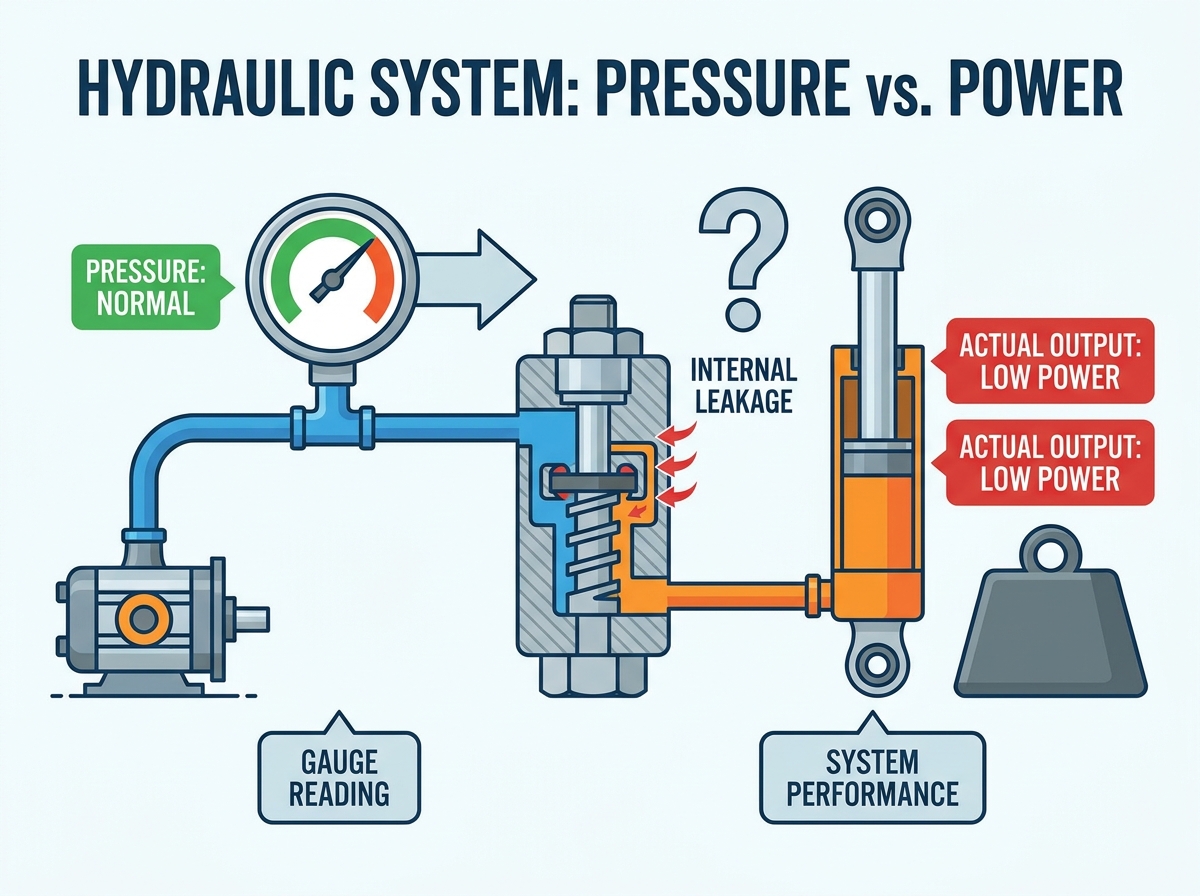
Operators and maintenance technicians often face a frustrating scenario on the job site. A machine registers completely normal pressure on the gauge, yet it stalls, moves sluggishly, or fails to generate the required force under load. The gauge indicates the circuit is fully pressurized, creating a deceptive illusion of machine health. This specific symptom frequently leads to costly misdiagnoses. Maintenance teams commonly assume the pump has failed and proceed with an unnecessary replacement. Swapping a perfectly functional pump results in extended downtime, wasted maintenance hours, and depleted parts inventories, all while the original problem persists.
To resolve this issue, technicians must apply a systematic, evidence-based diagnostic framework. The root cause of power loss despite normal pressure usually involves internal leakage, fluid bypassing, or localized valving failures. By isolating components and measuring flow rather than just pressure, you can pinpoint the exact source of the failure. This approach allows teams to evaluate repair versus replacement options effectively and restore machine performance without relying on guesswork.
Pressure Does Not Equal Power: Hydraulic power is the product of both pressure (force) and flow (speed). A system can hold static pressure while losing the dynamic flow required to do work.
Internal Bypassing is the Primary Suspect: When pressure is normal but power is low, fluid is likely taking the path of least resistance back to the reservoir via worn valves, loose manifold plugs, or degraded cylinder seals.
The Pump is Rarely the Culprit: Pumps create flow, not pressure. If the system reaches normal pressure, the pump is generally functioning; the issue lies downstream.
Port Relief vs. Main Relief: A single failing port relief valve can disable one specific actuator function while the main system pressure gauge continues to read completely normal.
Systematic Isolation is Required: Accurate diagnosis requires step-by-step isolation (such as deadheading components and measuring case drains) to identify the exact point of internal leakage without relying on guesswork.
Table of Contents
Static pressure readings differ significantly from dynamic pressure readings. A gauge mounted at the pump outlet or main manifold block measures the resistance to fluid flow at that specific location. It does not measure the volume of fluid successfully reaching the actuator. When a cylinder stalls under a heavy load, the fluid encounters maximum resistance, causing the pressure gauge to spike to the relief setting. The gauge simply confirms that the fluid is blocked from moving forward. It offers no confirmation that the fluid is actually performing mechanical work. Relying solely on a single gauge reading is a common trap for inexperienced technicians.
To understand what is actually happening inside the circuit, you have to look at flow. Flow is what moves the cylinder or turns the motor. If fluid is taking a shortcut back to the tank through a worn valve, the gauge will still show high pressure because the fluid is backing up against the restriction of that worn valve. However, the actuator receives a fraction of the required fluid volume. This is why a machine can show 3000 PSI on the dial but refuse to lift a load.
Understanding machine performance requires looking at the mathematical relationship governing fluid power. Hydraulic power equals pressure multiplied by flow, divided by a standard constant. Pressure provides the force, while flow provides the speed. If internal leaks cause a severe drop in flow reaching the cylinder, the mathematical output of power drops drastically. The pressure variable can remain at the system maximum, but without sufficient flow, the actuator cannot move the load.
Consider a loader lifting a bucket of wet dirt. The cylinders need a specific volume of oil per minute to raise that bucket at a usable speed. If half of that oil bypasses a worn spool valve and dumps back into the return line, the cylinders only get half the oil. The pressure gauge still reads maximum because the load is heavy, but the power output is cut in half. The machine feels weak and unresponsive.
Hydraulic fluid is generally considered incompressible, but the introduction of air changes its physical properties. Entrained air or foaming alters the bulk modulus of the fluid, making it highly compressible. When the pump attempts to move aerated fluid against a load, the energy is wasted compressing the air bubbles rather than moving the cylinder. This compressibility causes spongy operation and severe power loss.
Aeration usually stems from a suction line leak between the reservoir and the pump inlet. A loose hose clamp or a degraded O-ring allows the pump to pull in air along with the oil. The static pressure gauge may still register normal parameters during a spike, masking the underlying fluid condition. You will often hear a distinct whining or rattling noise from the pump when aeration is present. Checking the reservoir for foam is a mandatory first step before tearing into any valves.
Internal leakage occurs when pressurized fluid escapes from the high-pressure circuit directly into the low-pressure return circuit without doing mechanical work. Wear, fluid contamination, and thermal degradation accelerate this internal bypassing. Technicians often overlook mechanical culprits hidden deep within the circuit. Loose internal manifold plugs, blown cartridge valve O-rings, and channel-to-channel bypassing within solid manifold blocks allow fluid to take the path of least resistance back to the tank.
Contamination is the primary driver of internal leakage. Microscopic particles of dirt or metal act like sandpaper, scoring the tight clearances inside valves and cylinders. Over time, these scratches become channels for high-pressure fluid to escape. Even a scratch the thickness of a human hair can bypass a significant amount of oil at 4000 PSI. Regular fluid analysis and strict filtration maintenance are the only ways to prevent this type of wear.
Directional control valves direct fluid to the appropriate actuator ports. Spool wear, scored valve bodies, or failing internal centering springs compromise the tight tolerances required to seal high-pressure fluid. When these tolerances open up, fluid bypasses directly across the directional valve to the tank line. A clear sign of valve bypassing is localized heat generation. The energy lost through the pressure drop across the internal leak converts directly into heat, making the valve body noticeably hotter than surrounding components.
Use an infrared thermometer to scan valve bodies during operation.
A valve that is significantly hotter than the ambient fluid temperature is likely bypassing internally.
Check the manual override pins; if they feel spongy or fail to fully stroke the spool, internal debris may be preventing full closure.
Compromised piston seals allow fluid to bypass from the cap end to the rod end of a cylinder. This equalizes the pressure on both sides of the piston, effectively stalling the cylinder under load. Hydraulic motors suffer from similar internal wear. Worn rotary groups, damaged piston shoes, or scored valve plates allow fluid to bypass directly to the motor case drain. This starves the motor of the flow needed to generate rotational torque, even while the main input pressure remains normal.
Cylinder bypassing is often misdiagnosed as a weak pump. If a boom cylinder has blown piston seals, the oil simply flows past the piston and back to the tank. The pump is working perfectly, but the cylinder cannot hold the load. A simple deadhead test will confirm if the seals are intact.
A main relief valve stuck partially open, fatigued, or set too close to the operating pressure will prematurely vent flow back to the tank during dynamic operation. It is necessary to distinguish between the main system relief valve and individual port relief valves. A failing port relief valve affects only the specific circuit it protects. This failure causes a single function to lose power while the rest of the machine operates perfectly and registers normal operating pressure.
A foundational principle of fluid dynamics states that pumps create flow, while resistance to that flow creates pressure. If the machine can achieve normal pressure readings on the gauge, the pump is successfully moving fluid against a restriction. This fact generally rules out the pump as the primary failure point. A completely failed pump cannot generate the flow necessary to build pressure against the relief valve.
When a technician sees a machine lacking power, the immediate reaction is often to order a new pump. This is a costly mistake. You must prove the pump is bad before replacing it. If the main relief valve is set to 3000 PSI and the gauge hits 3000 PSI when you stall a cylinder, the pump is doing its job. The problem is that the flow is going somewhere else after it leaves the pump.
Pump evaluation becomes necessary only under specific edge cases. Severe cavitation, aeration, or catastrophic internal pump wear can cause the volumetric efficiency to drop significantly. In these rare instances, the internal slip is so high that the pump cannot overcome minor downstream leaks under high load. However, these conditions usually present with excessive noise, extreme heat at the pump casing, and metal debris in the filters.
Symptom | Likely Component Failure | Diagnostic Action |
|---|---|---|
Normal pressure, single function weak | Port relief valve or cylinder seals | Deadhead cylinder, check port relief setting |
Normal pressure, all functions weak | Main relief valve or directional valve bypass | Test main relief with flow meter |
Low pressure, excessive pump noise | Pump cavitation or aeration | Check suction lines and fluid level |
High heat at specific valve block | Internal spool bypass | Scan with infrared thermometer, isolate valve |
Establish the path of least resistance for troubleshooting. Test easily accessible external valves and cartridge reliefs before performing invasive actuator teardowns or draining large fluid reservoirs. This approach saves hours of labor and prevents the introduction of contamination into previously sealed circuits.
Verify fluid levels, viscosity grade, and physical condition before attaching any gauges. Inspect the reservoir for aeration, indicated by foaming or milky fluid. Measure the fluid temperature accurately. Excessive heat reduces fluid viscosity, which exponentially increases internal leakage rates across all components in the Hydraulic System.
Isolate the directional valve by capping the A and B work ports. Actuate the valve and monitor for pressure drops or excessive return flow to the tank line. If flow continues to the tank while the ports are blocked and the valve is shifted, the spool clearance is compromised, confirming internal bypassing.
Check the relief valve setting using a calibrated flow meter and pressure gauge, utilizing a load valve to simulate system resistance. Inspect and clean the cartridge nose, seat, and pilot orifice. Even microscopic debris can prevent the poppet from seating properly, allowing high-pressure fluid to leak continuously to the tank.
Perform a cylinder bypass test by deadheading the cylinder at the end of its stroke. Disconnect the return line and measure any flow coming out of the return port while applying pressure to the opposite side. For hydraulic motors, disconnect the case drain line, run the motor under load, and measure the bypass flow against OEM specifications. Zero or minimal leakage indicates healthy seals, while high flow confirms internal bypassing.
Compare the upfront cost of resealing cylinders and valves versus the long-term reliability of installing new OEM components. Rebuilding a cylinder takes time and requires a clean environment, but saves capital expenditure. Replacing a complex proportional valve is often more reliable than attempting a field rebuild. Standardizing replacement parts across a fleet reduces future diagnostic time and inventory complexity.
Evaluate transitioning from standard nitrile seals to Viton or Polyurethane if internal leakage is a recurring issue due to heat or aggressive duty cycles. Upgrading to tighter-tolerance valves can also reduce baseline internal leakage, improving overall machine efficiency and responsiveness under heavy loads.
Deciding whether to spend four hours rebuilding a valve or thirty minutes swapping in a new one depends entirely on the hourly cost of machine downtime. Calculate the lost production revenue per hour. If the downtime costs exceed the price of a new component, immediate replacement is the only logical choice to restore production.
Deadhead testing and cracking fittings present severe risks of injection injuries and burst lines. Mitigate these hazards through strict adherence to lockout/tagout procedures. Use properly rated diagnostic gauges and wear fluid-resistant personal protective equipment. Always bleed residual pressure from accumulators and trapped lines before loosening any connection.
Opening a circuit exposes it to environmental dirt. Introducing contamination during a valve or cylinder swap will rapidly destroy downstream components. Clean all fittings and surrounding areas thoroughly before disassembly. Cap all open hoses immediately and filter all new fluid before adding it to the reservoir.
Established in 2016, MDP is a Qingdao-based industrial and trade enterprise specializing in hydraulic valves, pumps, motors, power units, components, and accessories. With integrated quality management from design through delivery, ISO 9001-based testing, and custom engineering support, the company provides reliable hydraulic solutions for demanding industrial applications.
Start diagnostics by measuring flow and isolating components with a flow meter, rather than trusting static pressure gauges alone.
Perform deadhead tests on cylinders and case drain checks on motors to definitively identify internal bypassing.
Inspect and clean relief valve cartridges for debris before assuming a major component failure has occurred.
Factor the hourly cost of machine downtime into your decision to rebuild versus replace failing parts to maximize uptime.
A: The gauge shows the resistance to flow, not the volume of flow. Internal leaks in valves or cylinder seals allow fluid to bypass back to the tank. The system reaches maximum pressure against the restriction, but lacks the fluid volume required to physically move the heavy load.
A: Cap the A and B work ports on the valve. Shift the valve manually or electrically. If the system fails to reach relief pressure or you hear fluid rushing back to the tank line, the internal spool clearances are worn and fluid is bypassing.
A: It is highly unlikely. Pumps create flow. If the system can build maximum pressure against a load or relief valve, the pump is generating sufficient flow to overcome minor leaks. Pump failures typically result in a complete inability to build pressure.
A: A deadhead test involves extending a cylinder to the end of its stroke. The return line is disconnected and left open to a bucket. Pressure is applied to the extend port. If fluid flows out of the open return port, the internal piston seals are leaking.
A: Foaming indicates aeration, meaning air has entered the fluid. This usually happens through a suction line leak, low fluid levels, or improper return line placement. Aerated fluid becomes compressible, causing spongy actuator movement and significant power loss under load.
A: Disconnect the case drain line from the motor and route it into a measured container. Run the motor under a normal load for a specific time. Compare the volume of oil collected in the container against the manufacturer's maximum allowable case drain flow specifications.